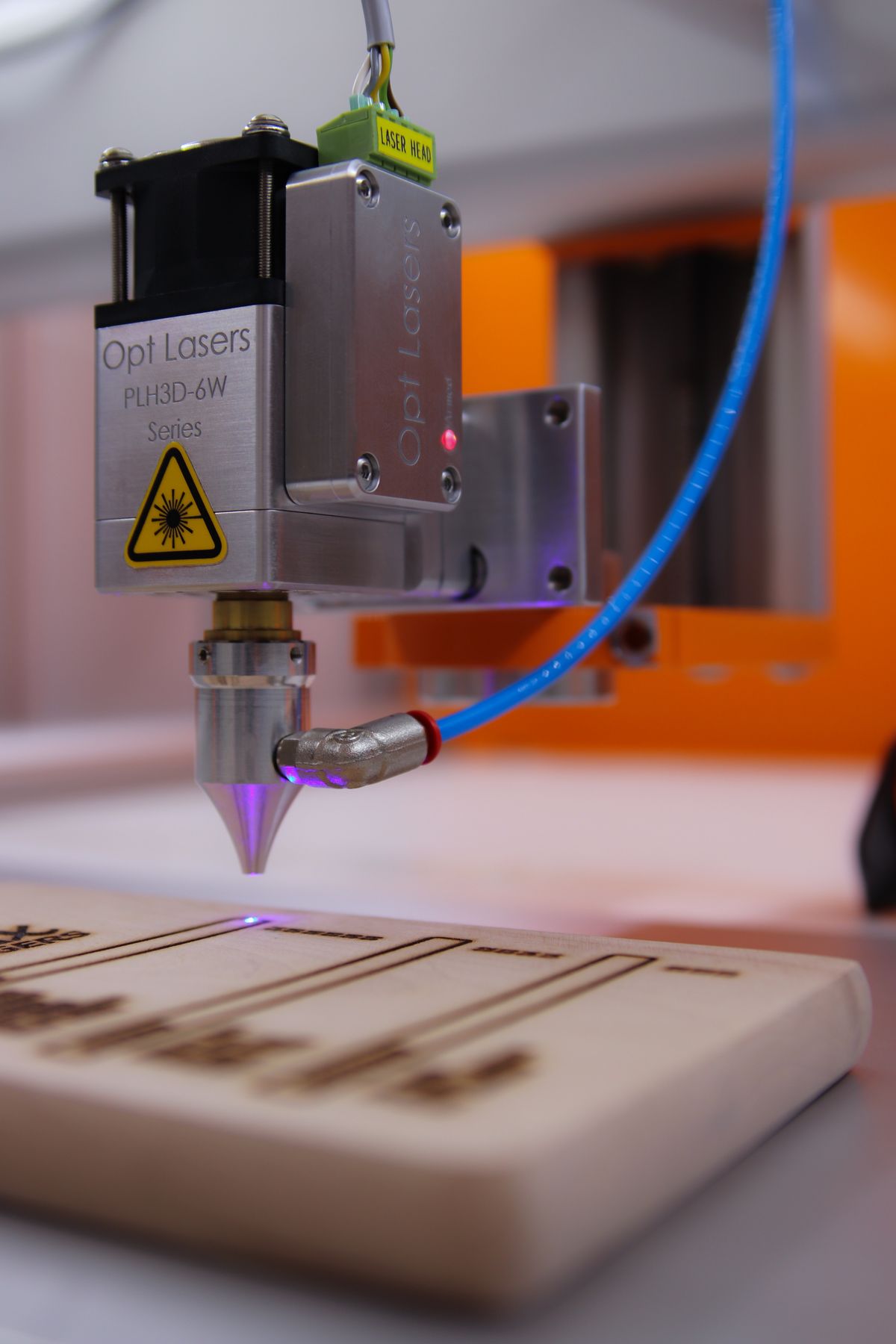
Converting a PNG or JPG to DXF can be a useful first step toward making a laser-cut sign, decorative panel, stencil, or logo. However, a successful conversion is not the same as a production-ready cutting job.
The image contains visible pixels. The laser workflow needs geometry that tells the machine where to move. Before cutting, that geometry must have the correct scale, suitable contours, and a clear relationship to the material and the intended finished object.
This guide explains how to convert an image to DXF for laser cutting, what to inspect after conversion, and which decisions still belong in your cutting software.
Decide which parts should be cut
Begin by separating the appearance of the image from the structure of the finished object.
A logo may contain colored fills, gradients, shadows, and highlights. Those visual effects do not automatically describe useful cutting boundaries. A metallic emblem, for example, may contain many bright and dark regions even though you only need its outer silhouette.
Decide whether your project requires:
- Only the outside contour.
- An outside contour with internal openings.
- Separate pieces that will be assembled.
- A stencil with connected sections.
- A combination of cutting and engraving.
This decision affects how you prepare the image. If you trace every visible color boundary without considering the final object, you may produce lines that should never be cut.
Use the original vector when available
If the design already exists as an SVG, converting it directly is usually preferable to rasterizing it and tracing it again.
Use SVG to DXF to work from existing vector geometry. This avoids introducing an additional interpretation of pixel edges.
Check the SVG before conversion. Live text may need to be converted to outlines, and strokes or special effects may need to be expanded in a vector editor. A design that looks correct on screen can still contain elements that do not translate directly into the receiving CAD format.
When a raster image is your only source, the preparation steps below become especially important.
Prepare a clear image for tracing
A clean, high-contrast image gives the converter a clearer boundary to follow.
Crop unrelated content, remove unnecessary shadows, and choose a source with enough detail to distinguish the narrowest features. Avoid screenshots that include a surrounding interface or a textured background.
For a silhouette, a transparent PNG can make the intended shape easier to identify. If needed, use Remove Image Background to isolate the subject, then inspect the edges before continuing.
A JPG can also be usable when the shape contrasts clearly with a plain background. Compression artifacts and soft shadows may create unwanted contour details, so compare the result carefully.
Do not expect a photograph of a three-dimensional object to produce a complete manufacturing drawing. An image trace reconstructs visible boundaries; it does not infer hidden geometry or engineering dimensions.
Convert the image to DXF
Open Image to DXF and upload your prepared image.
Choose the available settings according to the source. The aim is to identify the intended shape without collecting unrelated background detail. Set the full image width to the physical size you want to use, then generate the result.
Inspect the contour preview before downloading. Look for missing sections, extra islands, rough diagonal edges, and openings that have disappeared.
If the trace follows the wrong features, return to the source preparation rather than repeatedly accepting poor geometry. Removing a shadow or choosing a cleaner image can be more effective than trying to repair hundreds of unwanted contour segments.
Download the DXF once the preview reasonably matches the intended cutting outline.
Verify the dimensions after importing
Import the DXF into your CAD or laser software and check a known dimension immediately.
Do not judge scale from how large the drawing appears on screen. Applications can display different zoom levels, and import workflows may interpret units differently.
If the intended image width is 100 mm, confirm the appropriate 100 mm measurement in the receiving application. Then measure a second feature, such as the height or a known opening.
Pay attention to blank margins in the original image. The full image width and the width of the visible artwork are not necessarily identical. If a 100 mm image includes substantial empty space on both sides, the actual logo will be narrower.
For dimension-sensitive work, crop deliberately and verify the visible geometry after import.
Inspect closed contours and internal openings
Closed contours are important when the project depends on a complete boundary. A tiny gap can affect how cutting software interprets the shape or assigns an operation.
Zoom in on corners and intersections. Check that lines meet where they should and that the outline does not contain unexpected breaks.
Then review the internal openings. Letter counters, decorative holes, and enclosed spaces must remain present if they are part of the design.
Remember that enclosed pieces can become loose after cutting. In a stencil, the center of a letter such as “O” needs a connection to the surrounding material if it must stay in place. That connection is a design decision, not something that follows automatically from tracing the image.
Remove duplicate and unnecessary geometry
Overlapping or duplicate contours can cause repeated machine movements along the same location. Depending on the setup, that can increase cutting time and affect the material.
Use the inspection or cleanup tools in your receiving software to identify duplicated segments, very short fragments, and unintended overlaps.
Also examine small disconnected objects. A trace may include an isolated dot that belongs in the logo, or a tiny piece of image noise that does not. Their visual size alone does not tell you which is correct.
Review sharp points and narrow sections. A feature that looks attractive in the drawing may be too fragile for the material, particularly after the surrounding waste is removed.
Handle kerf and fit in the production workflow
The laser removes a finite width of material, commonly called kerf. This matters when parts must fit together or when a finished opening needs a specific dimension.
Converting the image to DXF does not automatically calculate the correct allowance for your machine, material, and settings.
Apply the appropriate compensation in your CAD or cutting workflow, taking care not to apply it twice. A file that has already been offset and then receives another compensation can produce the wrong dimensions.
For slots, tabs, press-fit connections, or other close-fitting features, make a small test piece before cutting the complete design.
Assign cutting and engraving operations deliberately
After importing, confirm which paths belong to each operation. An outline intended for cutting should not accidentally become an engraving boundary, and a decorative line should not be treated as a through-cut.
Review the operation order in the software’s preview. Check internal features and outside boundaries according to the requirements of your setup.
Use material-specific settings supplied or validated for your machine. The DXF itself does not determine a safe or effective combination of power, speed, focus, and number of passes.
Make sure the material is approved for laser processing and follow the equipment manufacturer’s operating and safety instructions.
Run a final preview and test cut
Before starting the full job, check the geometry, dimensions, placement, and operations together.
A useful final review includes the outer silhouette, internal openings, smallest features, duplicate paths, and the drawing’s position relative to the material.
Where practical, test a representative section. A small sample containing a curve, a corner, and a narrow opening can reveal problems before you commit the entire sheet.
Keep the source image and the reviewed DXF. If you need an SVG version for another editing workflow, DXF to SVG can help move supported two-dimensional geometry into an SVG file.
Frequently asked questions
Can I use any JPG for laser cutting?
You can trace suitable JPG images, but a photograph or heavily compressed logo may not contain clear cutting boundaries. Prepare the intended silhouette first.
Does a DXF contain the laser settings?
A converted DXF primarily supplies drawing geometry. You still need to assign the correct operations and machine settings in your production software.
Why is my imported DXF the wrong size?
Check the import units, the width used during conversion, and any blank margins in the source image. Confirm a known measurement rather than relying on the on-screen appearance.